Simplifying accelerator integration for FPGA-based edge AI solutions with Accelerator Interface Generator
Published:
Topics: Open source tools, Open FPGA
Given the rising demand for AI processing on the edge along with rapid advances in AI model compression through pruning and quantization to 8-bit, 4-bit (and even lower) integers, the configurability, low power and latency offered by FPGAs make them an interesting platform for building secure local AI solutions that can evolve over time both in terms of hardware and software.
This configurability does come with some complexity, however, and integrating AI accelerators in FPGA systems manually can be a tedious and error-prone task, involving a detailed understanding of the intricacies of the internals and operation of FPGA devices. To build an AI accelerator in an FPGA, on top of devising the accelerator and software infrastructure around it, you may need to interface with units handling data transfers (such as DMAs), establish a Control/Status Registers infrastructure as well as integrate the developed accelerator system with a selected FPGA device. To simplify this process, Antmicro has been developing a framework called Accelerator Interface Generator (AIG) as part of the EU-funded VEDLIoT project.
Below, we offer an overview of the AIG tool, detailing its implementation, as well as the testing and verification capabilities it offers. We guide you through the process of building your own accelerator interface step-by-step. Additionally, we present a preview of upcoming support for the Pipeline Manager tool which introduces a user-friendly graphical interface for configuring accelerator systems.

Accelerator Interface Generator
Accelerator Interface Generator is a configurable and vendor-independent tool designed to integrate any accelerator implementing an AXI4-Stream interface with FPGA DMAs. This resulting accelerator-DMA system can then be incorporated onto a selected FPGA target device, providing a ready-to-use data-processing pipeline that can be utilized both on hardware and in simulation. The tool’s main aim is to provide an automated approach to integrating AI accelerators to ensure the produced design is FPGA platform-agnostic and does not require using any particular software but rather works as part of your AI framework of choice.
AIG relies on Antmicro’s FastVDMA for performing data I/O operations between a user-defined accelerator and the main memory independently of the CPU. FastVDMA is an open source DMA controller that provides an alternative to proprietary controllers supplied by FPGA vendors, while also allowing for significant customization.
Currently, AIG offers support for AXI4 and Wishbone for data transfers using FastVDMA.
In order to provide a communication interface with the integrated accelerator, AIG allows users to specify custom Control/Status Registers (CSRs). Control registers can be used to manage accelerator settings or initiate specific actions, whereas status registers usually provide information on the accelerator’s current state or conditions. Together, they allow the software (i.e. device drivers) to interact with the core via reads/writes to assigned memory regions.
Currently, three different types of CSRs are implemented:
- Status Register - read-only
- Auto-Clearing Register - read-write; clearing the register once a write request has finished
- Storage Register - read-write; overwrites with each write.
These custom CSRs are specified using the AIG configuration file. Once defined, the accelerator is equipped with a dedicated control bus responsible for managing access to the accelerator’s CSRs. Just like in the case of FastVDMA, AIG currently implements the AXI4-Lite and Wishbone protocols for control buses.
The accelerator’s control bus is connected to the decoder of the corresponding bus type and the decoder facilitates transmission of a CSR operation between the system’s main bus and the relevant component (one of FastVDMA blocks or the accelerator).

Implementation overview
At the core component of the AIG project is the design written in Chisel, a parametrizable Scala-based hardware description language. It includes CSR definitions, implementations for CSR handling buses, AXI4-Lite and Wishbone decoders, as well as a FastVDMA integration.
For a user-defined accelerator, AIG provides a set of tools that, based on AIG’s configuration and the accelerator’s design, generate custom CSR definitions and a so-called Chisel BlackBox of the accelerator design, allowing it to be later integrated with the FastVDMAs and CSRs infrastructure. As blackboxes are essentially a method of porting externally defined modules into a Chisel design, they also allow users to easily exchange accelerators within an AIG-based project.
Lastly, another set of crucial tools is responsible for generating target FPGA device descriptions, including the created accelerator system, based on its target device configuration. The configuration allows for adjusting elements such as the base address of the AIG region, the CPU, and other target-specific parameters.
AIG configuration
The entirety of AIG customization is specified with a JSON configuration file that specifies bus protocols for handling CSRs and I/O operations.
“busConfiguration”: “bus-in_bus-csr_bus-out”
The bus-in and bus-out segments in busConfigurations are abbreviations for bus protocols to be used for reading (bus-in) and writing (bus-out) data to the main memory, with WB (Wishbone) or AXI (AXI4) available as options. The bus-csr segment corresponds to the type of control bus to be used, with the available selection of WB (Wishbone) or AXIL (AXI4-Lite).
The crucial element of the configuration is the accelerator section, comprising general information about the accelerator, such as the Verilog source file’s name (sourceFile), address/data widths (addrWidth, dataWidth, …) and mappings (signals) for AXI4-Stream (input and output properties), reset and clock signal.
“accelerator”: {
	“sourceFile”: <accelerator.v>,
	“topName”: <accelerator>,
	“params”: {
		“addrWidth”: <addrWidth>,
		“dataWidth”: <dataWidth>,
		“controlAddrWidth”: <controlAddrWidth>,
		…
},
“signals”: {
	“clock”: <clock>,
	“reset”: <reset>,
	“input”: {
		“tdata”: <tdata>,
		“tvalid”: <tvalid>,
		…
},
“output”: {…}
}
	“csr”: [...]
}
Optionally, custom CSRs can be also defined for the accelerator.
"csr": [
{
    		"name": <csrName>,
    	"type": <csrType>,
    		"address": <csrAddress>,
    	"fields": [
        			{
            	"name": <fieldName>,
            	"type": <fieldType>,
            	"direction": <fieldDirection>,
            	"size": <fieldSize>
        	},
        		…
    	]
	},
]
Each CSR can be specified with a unique name, type, relative address and fields. AIG allows aggregation of multiple fields within a single CSR, with each field name aligning with the signal name in the accelerator’s top Verilog module.
Target FPGA device configuration
In order to configure the target FPGA device, users need to specify the name of their device (targetDevice), the CPU used with it (cpu), the systemClockFrequency, the AIG baseAddress and the path to the AIG configuration file (aigConfigPath).
Additionally, the configuration allows for additional, target-specific arguments to be passed to the SoC generator.
"targetDevice": <targetFPGADevice>,
"cpu": <CPU>,
"systemClockFrequency": <freq>,
"baseAddress": <baseAddress>,
"aigConfigPath": <path/to/aig-config.json>,
"socArgs": [
{
"name": <argName>,
        	"value": <argValue>
    	},
	…
]
…
Testing AIG-produced designs
AIG offers sample test suites that illustrate the available approaches for testing an AIG generated system. The provided tests utilize the AIG system with FPGA ISP cores as a sample accelerator. FPGA ISP is a collection of ISP cores dedicated for real-time video processing in FPGAs, implementing several demosaicing algorithms that interpolate frames from Bayer to RGB format. Both tests simulate an image transfer through the sample accelerator.
AIG provides a bus-configuration-independent test suite that utilizes the cocotb framework, a coroutine-based co-simulation testbench for verifying VHDL and SystemVerilog RTL, written in Python. The cocotb testbench provides AXI4, AXI4-Lite, AXI-Stream, and Wishbone bus support via its cocotbext-axi and cocotbext-wishbone extension.
This testbench can be easily adjusted to fit the needs of any accelerator system. The AIGTestInterface class provides integration between AIG buses and cocotb’s respective bus models.
######## AIGTestInterface ########
aig = AIGTestInterface(dut, cfg) # where cfg is bus-in_bus-csr_bus-out
An accelerators’ control / status registers can be interacted with using the write_csr and read_csr methods. In the case of the FPGA ISP accelerator, the CSRs need to be set with values corresponding to the interpolation algorithm, the input frame pattern, the output image format (RGB or BGR), and the frame’s dimensions:
######## Setup Accelerator ########
await aig.write_csr(base_addr_acc, ((0x1 << 0x8) | (0x0 << 0x4) | 0x1))
await aig.write_csr(base_addr_acc + 0x4, (height << 0xd) | width)
FastVDMA also contains information about transfers in the CSRs:
######## Setup input DMA ########
await aig.write_csr(DMARegisterMap.ReaderStartAddr + base_addr_dma_in, 0)
await aig.write_csr(DMARegisterMap.ReaderLineLen + base_addr_dma_in,
                	(height * width) // 4)
await aig.write_csr(DMARegisterMap.ReaderLineCnt + base_addr_dma_in, 1)
await aig.write_csr(DMARegisterMap.ReaderStride + base_addr_dma_in, 0)

await aig.write_csr(DMARegisterMap.WriterStartAddr + base_addr_dma_in, 0)
await aig.write_csr(DMARegisterMap.WriterLineLen + base_addr_dma_in,
                	(height * width) // 4)
await aig.write_csr(DMARegisterMap.WriterLineCnt + base_addr_dma_in, 1)
await aig.write_csr(DMARegisterMap.WriterStride + base_addr_dma_in, 0)
The Reader* registers correspond to the interface of the DMA that is transferring data from the main memory to the accelerator and the Writer* ones correspond to the interface that writes to the main memory. Each transfer needs to be specified with the address and size of the data, and optionally – stride. A detailed description of FastVDMA CSRs can be found in the Register Fields section of the controller’s documentation.
FastVDMA is run by writing to the Ctrl register and will raise an interrupt at the end of the transfer. IThe interrupts are enabled by writing to InterruptMask:
######## Run DMAs  ########
# Enable interrupts
await aig.write_csr(DMARegisterMap.InterruptMask + base_addr_dma_out, 0x3)
# Run in loop mode
await aig.write_csr(DMARegisterMap.Ctrl + base_addr_dma_out, 0xf)

await aig.write_csr(DMARegisterMap.InterruptMask + base_addr_dma_in, 0x3)
await aig.write_csr(DMARegisterMap.Ctrl + base_addr_dma_in, 0xf)
It is also possible to create a test suite with Chisel’s dedicated testing and verification package - chiseltest. FastVDMA implements several Bus Functional Models that provide high-level abstraction for certain bus protocols (similarly to the bus models provided by cocotb extensions), allowing for the AIG system tests to focus on the purely functional aspects.
A chiseltest approach to AIG system test case is defined within the ImageTransfer class. After the transfer is completed, the output image is written to a file, making it easily verifiable, and the waveforms from the test are saved in an fst-format file.
Step-by-step accelerator integration with AIG
Accelerator implementation
In order to use AIG, you will need an accelerator implementation in Verilog which supports AXI Stream interface for data I/O. For instance, you may use the FPGA ISP cores accelerator example provided with the AIG.
Naturally, AIG’s support is not limited to image processing only, as it can be used with any AXI Stream-compatible data processing blocks.
Configuration
Once the accelerator implementation is obtained, AIG will need a configuration for the desired system to generate an accelerator integration. The configuration can be written manually with reference to the configuration guidelines.
Running AIG
AIG provides rules for different AIG stages in a makefile. Running the verilog target will produce an accelerator system in Verilog:
make verilog AIG_CONFIG=<path/to/config.json>
The AIGTop.v and accelerator source code file will appear in the project root directory. Both files constitute an accelerator system containing two FastVDMAs, CSR managing infrastructure, the accelerator itself and the integration between them.
The AIGTop module exposes control and data-transferring buses to allow further integration with the FPGA target device.
Generating target FPGA device description
AIG currently supports two FPGA target devices - Zynq Video Board (Zynq7000 SoC) and Arty A7 (VexRiscv CPU).
The target FPGA device description with AIG integration can be produced with the make target rule, assuming the AIG and target configuration files are provided.
make target AIG_CONFIG=<path/to/aig-config.json> TARGET_CONFIG=<path/to/target-config.json>
This will produce the aig_generated_target.py which can later be used as a target from the litex-boards project.
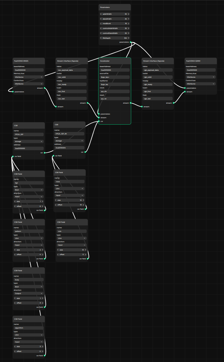
Pipeline Manager integration
The AIG is an actively developed project with prospects of expanding the support for more FPGA targets and further simplifying the process of deploying custom AI solutions on edge devices.
One of the upcoming updates includes introducing the support for the Pipeline Manager tool, which will let users construct accelerator integrations using a user-friendly graphical interface.
Below you can see a preview of a functionality - the Pipeline Manager editor (you need to use a desktop browser to see the interactive version) - depicting the accelerator along with its generated interface:
Prototype and test your FPGA-based edge AI solutions with Antmicro
The Accelerator Interface Generator can help use the flexibility of FPGAs to build tailored edge AI solutions. Antmicro can assist you in adopting the workflow proposed in this note together with other open source solutions available in our diverse portfolio, customize them to best match your company’s particular use cases, and build CI systems that include comprehensive testing on physical hardware as well as in simulation.
To discuss how we can help you build custom edge AI products or streamline your AI development, reach out at contact@antmicro.com.